Take 4.2 - PIC32 and PAL-based Approach (DMA)
Ok, so at this point I had a PIC32 microcontroller pushing pixels out to my TV at 8MHz via an Analog Devices AD724. I had decided at this point that manually pushing out pixels in software was not going to work for a real game. There was already jitter in each line of the display and attempting to weave in a graphics kernel amongst the port I/O was going to further increase jitter. So I decided it was time to switch to DMA.The DMA peripheral on the PIC32 is quite flexible. You can set up a timer and have it set the cadence of the DMA stream. The DMA engine will copy the data without further intervention leaving the CPU free to run game logic etc. The DMA can also run without a timer and as far as I can tell, this is only suitable for internal SRAM to SRAM transfers.
What I discovered was that when the DMA engine is driven by a timer the maximum rate it can manage is 3.7MHz. I still have no idea why this limit exists and I'd still love to be proved wrong. However, there is other independent evidence of this. This post on HackADay.com shows this limitation. You need to scroll all the way down to the DMA Performance section.
For some reason I don't have the source for the timer driven version but it is nearly identical to the Microchip PIC32 example here. The important parts are below:
DmaChnOpen(dmaChn, 0, DMA_OPEN_AUTO);
DmaChnSetTxfer(dmaChn, pixelData, (void*)&LATA, 64, 1, 1));
DmaChnSetEventControl(dmaChn, DMA_EV_START_IRQ(_TIMER_3_IRQ));
DmaChnEnable(dmaChn);

OpenTimer23(T2_ON | T2_SOURCE_INT | T2_PS_1_1, 10);

while(1) {}
This code sets up the DMA engine to transfer from pixelData to PORTA every time there is a timer rollover event on timer 3. Timer 2 and 3 are combined here to make a 32bit timer - which is unnecessary in this case. The OpenTimer23() call requests a rollover event after 10 cycles which at 80MHz is an 8MHz pixel clock. My pixelData array was 0x00, 0xFF, 0x00, 0xFF in a repeating pattern. My scope showed a 3.7MHz square wave. It should have been 8MHz. I have never understood where the restriction is.
I had another idea. The PMP peripheral was used on the Microchip LCC example. Perhaps is was required in order to exceed a 3.7MHz pixel clock. The LCC example is much higher than 3.7MHz. So I tried that. My understanding was that the PMP peripheral would request a DMA cell transfer as required - effectively pacing the DMA transfer. My cell size was set to one byte. My scope indicated I had achieved 6.25MHz. So the PMP peripheral was faster. I still don't know why. I suspect it has an internal buffer that hides some latency. I'm not sure.
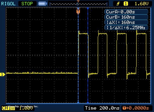
I tried setting the cell size to 2 and I got the following:

It appeared that I was each byte was output at 19.2MHz but there was a latency which made the overall rate about 10MHz. I couldn't use this on a TV. Every second pixel would be twice as wide!
I posted my issue on the Microchip forum but I wasn't able to solve it. Some very kind folks tried to help me on that forum. I think there are some very smart people lurking on that forum.
Sigh.
At this point I was ready to give up on the PIC32. I really liked the whole stack but I wasn't getting anywhere. Towards the end of 2014 I ordered an STM32F4 Discovery board. I was really dreading this. It takes a while to get up to speed on a new microcontroller and tools. I set myself a goal to grok the STM32 and get DMA working in under 4 weeks. It arrived on the 17th December 2014.
I'll cover the "fun" encountered with tooling and STM32 Standard Peripheral Library versus STM32 Cube in my next post.